OVERVIEW
(Last Edit 10/15/2020 08:17 AM)
Semiconductor factory renovation, Tool Installation (AKA TI) and LayOut Dependencies (AKA LOD) is an enormous undertaking, extremely fragmented and unfocused at times with many stakeholders focusing on their legacy production methods.
Within Intel any meaningful cost reduction has to include Layout. Bringing layout into present day technology is the keystone of any plan. All design drawings should have moved into 3D years ago instead of burdening trade contractors with modeling skills.
Establish an overall strategy & execution detail for the long term efficiency improvements to Intel Base Build, Layout Dependent, and Tool Install construction activities. Construction success is directly affected by comprehensive design documents and up to date processes.
Like all new and evolutionary technologies the foray into BIM was a minefield wrought with cost overruns and production loss. Any plan should mitigate situations where the trade contractors previously took advantage of many mismanaged circumstances.
Intel interest in technology security is well served by internally controlling design and offsite fabrication and managing tool installation. Such a properly executed scenario isolates outside teams from determining factory capacities.
A prime directive of any successful plan is to unify mindset of the stakeholders. We must transition their mindset, their perception of Intel management as the inhibitor of production to the enabler of production.
BIM’s key deliverable is a 3D geometrically realistic prototype developed to include all systems described as they would be built, reflecting final as built conditions. Common sense shall be the teams golden rule.
Subcontractors can install materials quicker by properly applying current metrology fabrication layout methods to eliminate shop drawings.
Create and implement reward oriented culture.
Reward based policies and methodology will be implemented. Restructure the concept of “Task Force” into actual resource and assistance allocation.
Apply indicators to meetings as to how productive they were based on the cost of the people, the cost of the subject you are meeting on, and the metrics used to make the decision. Replace clash review meeting with an automation program. Use programmatic automation to replace 14 to 17 persons who manage and compile graphical data files representing campus BIM models.
Customize entire design process: Establish a five year road map. Significantly improve or replace legacy AutoCAD software & layout processes with up-to-date software & methods.
Revise the design & as-built processes by using new metrology technologies. Real time photographic analysis allow a very fast and inexpensive way to validate designs and as-built conditions. 3D Disto allow remote operators to: take photos, measure visible points, and perform multipoint scans of areas. New metrology methods will be adopted for route verification and fabrication essentially replacing the creation of shop drawings. Fabrication will be done from approved issued for fabrication 3D models.
Contracts should expect any trade, at a minimum – regardless of scope – to provide 3 Dimensional centerline line routing information or solid / surface boundary geometry for any item placed in factory.
We’ve invested significantly in 3D routing of Process, Electrical, and Mechanical systems for legacy tool installs. Given the similarity of the Intel factories worldwide there is a reusable aspect to these tool & routing models. Together with our partners we should examine what we have and determine reusability.
Scripts, templates, programmatic solutions would be provided to designers and trade contractors to assist in creation & maintenance of mandated standards.
These files would complement current or previous INTEL BIM CAD Standards
Laser scan usage (if a viable method) will be used in a much smarter way, cubing or slicing or selective meshing to increase usefulness.
PROPOSED METROLOGY PROCESS
PHOTOGRAMMETRY:
Metrics indicate cameras taking multiple pictures used to create textured meshes is not viable for Intel construction services at this time. Process is time consuming, resource intensive and not able to be operated remotely.
ELECTRONIC DISTANCE METERS:
Metrology solutions must be simple to use, extremely resource efficient, compact, wireless, allow remote access via secure network, reasonably priced, and have a lifecycle of two tool install cycles.
IMAGERS & CAMERAS:
With that criteria in mind, deploying Leica 3D Distos laser distance meter, with a mix of Leica BLK3D imagers, and Arlo Ultra wireless cameras meet our initial needs.
| Item | Cost | Size (H x W x D) / weight | Description/Comments |
| 3D Disto Laser Distance Meter | $7500 | 7.36 x 8.48 in / 6.17 lbs | Point, scan, measure, photograph, (FOV @ 32 ft. No Zoom) 11.15 ft x 7 ft) Remote usage |
| BLK3D Imager | $5000 | 7.11 x 3.06 x 1.07 in / 17 oz | dimensional information, photograph (80deg FOV) No remote usage |
| Arlo Ultra webcam | $200 | 3.5 x 2 x 3.07 in / 11.67 oz | 180,130,110 Deg FOV 4K resolution (180 deg FOV) Remote usage |
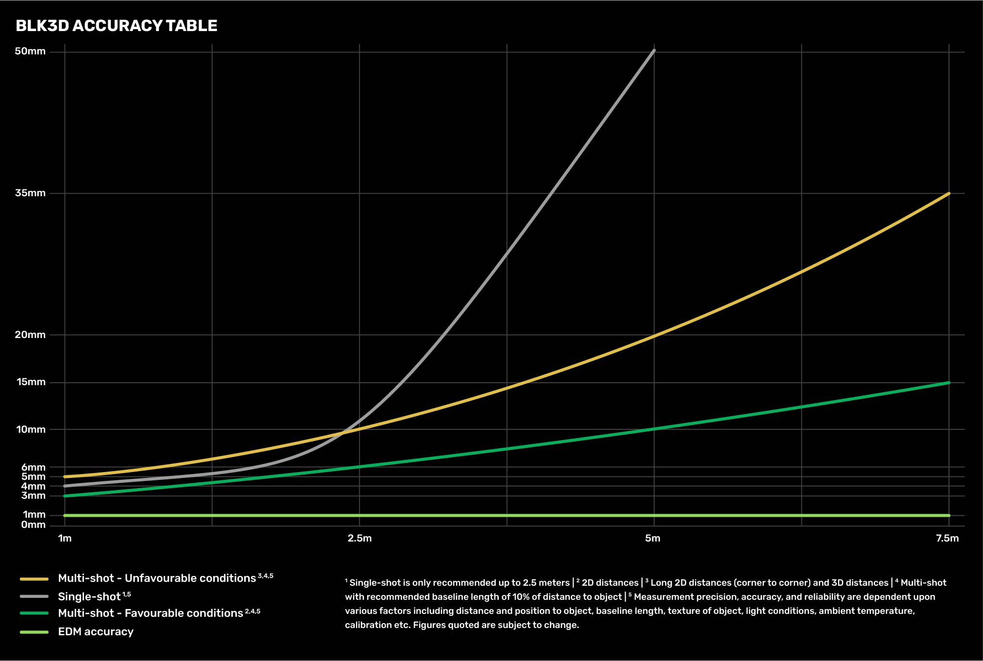
BLK3D Imager Accuracy Table
OVERVIEW OF USAGE PROCESS
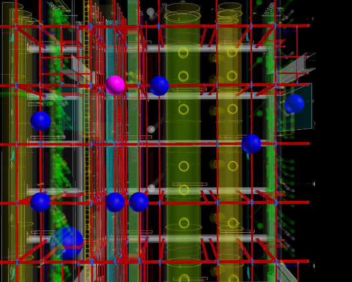
Qualified persons would deploy Distos & Cameras to fab, mounting them on the unistrut. Camera locations would be mapped manually allowing users to find the camera affording the best view of an area they are interested in.
3Ddistos, when resectioned , calibrate themselves to the fab control coordinate system. Resectioning is a process of sighting three known points, targets in the fab, and entering the coordinates of each point into the Disto.
Navis & Revit digital maps containing current locations of Cameras & Disto devices in each fab would be provided. Blk3D Imagers require an operator, who takes requests for information, providing pictures, and measurements transmitted wirelessly to the requester.
The files would be provided to Trades, Intel staff, and others permitted use by Intel. Interested parties would load/open the map and select a device, camera, 3D Disto, or Imager. Providing the user has security credentials, they would see the area with a camera, Disto, or Imager, and preform measurements with the Imager & Disto, but not the live cameras.
The Cameras and Distos would be accessible via network login/password. Process and approval to deploy wireless devices in subfab space will require approved process plan and deployment procedures. These devices will require low voltage power feeds to maintain internal batteries, thus a wiring plan is required.
A policy process will will allow orderly use of the resources by priority. This process is expected to be automated by allowing groups of user’s access based on time of day, or calendared appointments, in order to reduce network traffic response lag. The system has to remain “fast” to use.
Devices are expected to move around during tool install / LOD in order to monitor area of weekly concern. Entire “system” is deployable to next fab domestically or abroad for use in other fabs.
CLARIFICATION GRAPHICS
| Roxtec Routing Zone light cyan on Left, | Roxtec Routing Zone solid Pink on right |
|---|---|
 |
 |
| Vertical area above Roxtec membrane between subfab and utility level | Vertical area above Roxtec membrane between subfab and utility level |
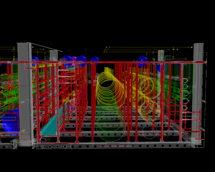
Devices can be mounted on unistrut to monitor and measure locations of vertical zones like the areas above roxtec.
| Unistrut column square | Unistrut column square closeup |
|---|---|
 |
 |
| Unistrut | Unistrut |
Unistrut is preferred anchoring frame for devices, approximately one 25’ square bay shown on left, with close-up on right.
| Device placement on unistrut, plan view | Device placement on unistrut, elevation view |
|---|---|
 |
 |
| Disto & web-cam placement | Disto & web-cam placement |
View of mocked up device placement shown as spheres, plan view on right, front view on left.
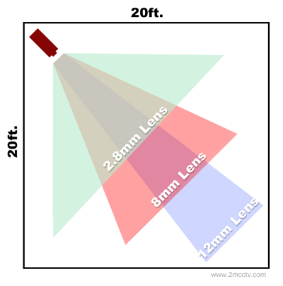
| Field of view diagram | Field of view mock up in subfab |
|---|---|
 |
 |
| FOV Diagram | Device FOV example |
Each device has it’s own Field of view (FOV), Graphic on left shows generic FOV diagram, while graphic on right shows narrow FOV (Like the 3D Disto) pointing down. Note objects obscuring view.
| 110 degree field of View shown | 130 degree field of view shown |
|---|---|
 |
 |
| 110 FOV Device FOV example |
130 FOV Device FOV example
|
Graphic on left shows generic 110 degree FOV for device mounted below Unistrut, while graphic on right shows a 130 degree FOV. Graphic shows wide range of observable area per device.
SUMMARY:
Cost is estimated as 5 million for the subfab area of Fab 42
BENEFITS:
Deploying network capable metrology devices, 3DDistos, Blk3D Imagers with 4K resolution cameras allows teams near real time access to Subfab information. Images and geometric measurements permit accurate background models. Small scans of areas can be taken in minutes and converted to representative geometry. Pipes, hangers, POC’s, cable tray, anything you can sight can be measured and located. The information can be deployed in minutes, accurate background models generated in hours. Physical access to subfab is significantly reduced if not eliminated.
Cost far lower than Laser scanning, capabilities flexible, accuracy excellent. A three person team can maintain, update and relocate devices throughout construction cycle. Equipment is small and deployable to other fabs for use with their construction cycles.
LIFECYCLE:
This solution suite should remain viable through two tool install cycles, and be deployable to sub fab areas in Ireland, Israel, Chandler, even Portland before end of life. All the equipment is small enough to pack up and move, then redeploy.
TRUE COST:
While I’ve attempted to consider all the factors, only a pilot conducted in a subfab will provide true cost vs value data to project actual costs.
FAST ACCESS TO ACCURATE INFORMATION:
This proposal is a solution permitting authorized users (i.e. Designers, Intel Layout, trades, coordinators, managers, any person permitted access) to log in “see & measure” the current subfab. Should the area of interest not be in the device field of view (visible or blocked from view) the device can be moved and active within minutes under normal conditions.
PROCESS GENERALITIES
Deploy & Maintain equipment – Assist in use
While initial deployment will have minimal usage instructions and training resources, actual usage will determine what procedures to address and what form that instructional resource will take. Resources are projected to be: direct tel-cons, on-line videos, HTML based documents, programmatic automation applications, chat, messaging, and facetime video access.
Team will take requests from select users for all forms of assistance. A hierarchal help system will be implemented with tiered priorities. Direct in person assistance shall be provided to tens of persons, not hundreds. Media based assistance in the form of on-Line help, tutorials, videos are expected to provide hundreds of users assistance.
EXAMPLE OF RESOURCE LOCATION:
Cameras, Distos and Imager files will have 1) naming sequence as Popout name, or column grid or some easy to reference sequence already in use.
A 3D file, where each camera, Disto, and Imager file if identified by its 3D Cartesian coordinate will be created and maintained.
Software tools for AutoCAD, Revit, Navisworks will be provided to locate resources near area of interest to user.
Network will be secured and hopefully a subnet of Intel’s wireless in fab. I’ve covered the cost of deploying a wireless mesh in the subfab as part of the solution.
EXAMPLE OF PHYSICAL DEPLOYMENT
Cameras and Distos will be anchored to unistrut, using unistrut connectors, and or magnet base clamps. Connections to unistrut shall be simple and mechanical, i.e. not sitting or resting, but firmly attached. Power wire shall be zip tied in position, and clearly labeled. Power will be taken from base of column power receptacles.
(Model Proposal)
PLAN POINTS
Extract objects from existing subfab area models
- Export parts, pipe section, unistrut, columns, gas valves, etc.
Organize and store those objects in database
- Object takes standardized name, definition is stored in database.
Implement organized objects in menu system native to Revit, AutoCAD flavors, Navis, etc, for use in building 3D subfabs
- Conversion of standardized database format into native Revit, AutoCAD or standardized file format (IGES, STP, STL, etc.)
Populate menu system from database.
- Use (probably python) to create native Revit, AutoCAD, menu add-on so users can select standardized object to maintain subfab model.
Ongoing QC of all objects with metrology equipment and methods, measurements, lightweight scans, pictures from imagers.
- Measure, photograph, keep current, all objects in database.
Secure document management systems for all objects
- Secure database on Intel system, or secure system with Intel technology.
Find voxelization system for all data so we can speed up rendering of areas (Links 1, 2, 3)
- Look into gaming solutions for using large unwieldy data sets of subfab models by trades, and designers.
Apply previous metrology solutions to process, i.e. measure and coordinate everything we can touch.
- Measure, photograph, keep current, all objects in database.
Decide on model format, create master model in that format
- Conversion of standardized database format into native Revit, AutoCAD or standardized file format (IGES, STP, STL, etc.)
Ongoing maintenance of subfab to keep current.