
Saturday, April 10, 2021, I performed a Google search on BIM failings. This action was prompted by Intel removing the BIM requirement (and BIM subsiding components) from their construction contracts.
The first two pages of search results clearly articulated problems I observed in every one of the projects I’ve historically been a part of. I would add the majority of the blame settles on the shoulders of people, specifically managers and executives.
What I did not find in my search was a “new” or “different” set of solutions to well documented BIM problems. Drilling down on the intent of my statement, the problems and their solutions dated from 2012 through 2019. We observed these same BIM failings and solutions during the Stanford CIFE VDC certifications in 2009-2010, twenty one years ago.
What follows below is my solution to some, not all BIM failings and takes a common sense approach to mitigating construction prefabrication, just in time construction with fewer people and less expensive equipment.
For more I recommend you preform a search using term "bim success factors".
Last rev: 10/14/2020 12:12:00 PM ( See Intel_Pilot_Report_2018.09.04.docx (link to PDF version) for on-site experiences and link to results in 3d graphic form)
We're not telling you it’s going to be easy, We're telling you it’s going to be worth it. No good comes from abandoning facts and reason.
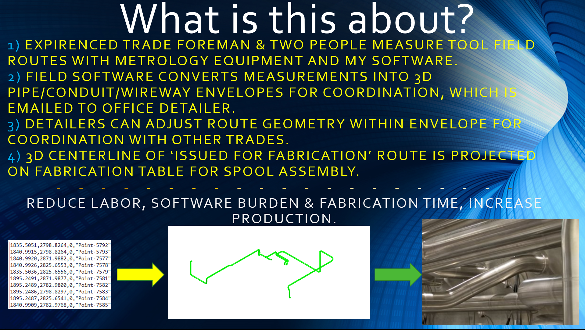
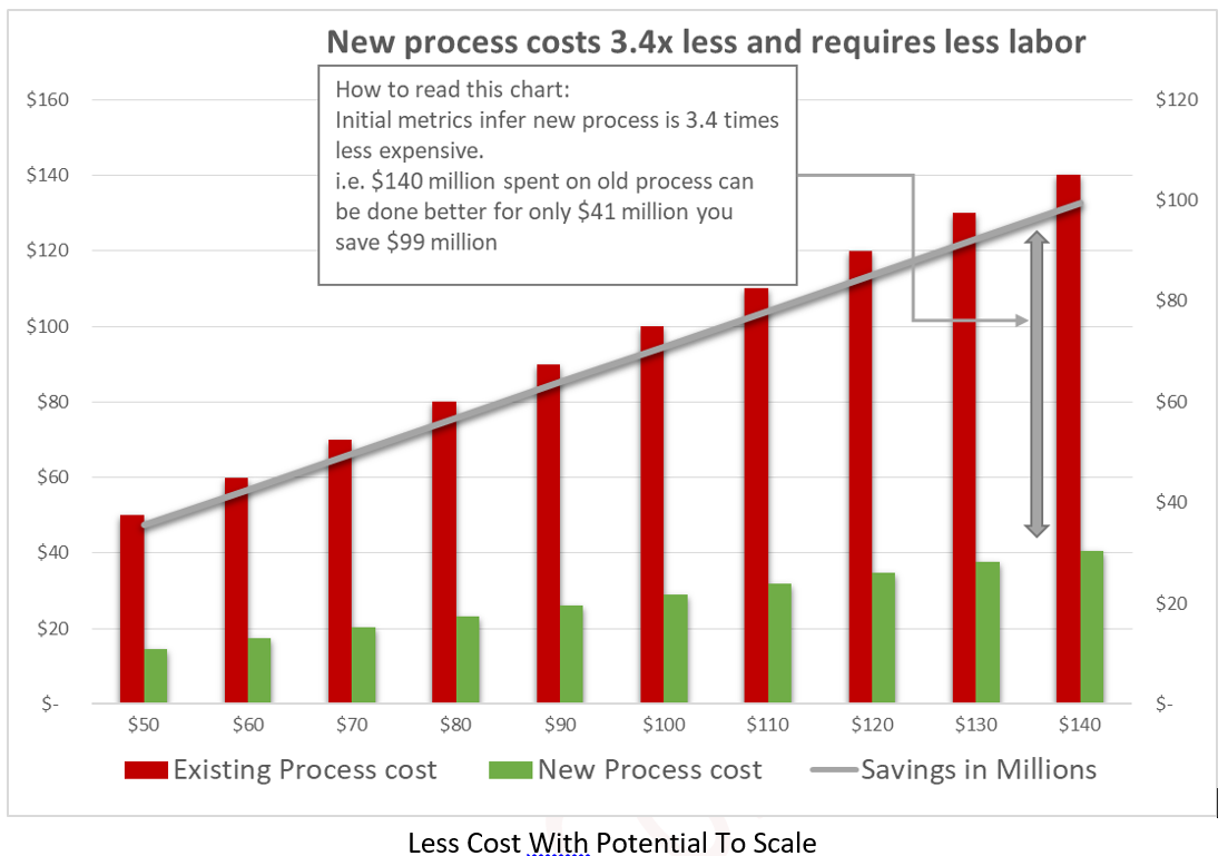
The message of this page is summarized in this single graphic. [STATIC IMAGE]
Move fabrication up, reduce detailed 3D modelling for coordination purposes, return more control to trades. Remove low value activity and costs from tool install supply chain. [STATIC IMAGE]
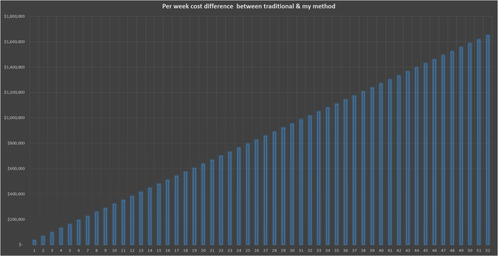
Cost difference of a 3 person laser scanning crew vs a 3D Disto crew. $31,675 a week, or $1.6 m in 52 weeks[STATIC IMAGE]
Intel Metrology Pilot rationale
Audio presentation of Pilot overview (no written content of this audio is below, 1 min 35 seconds)
If no audio player appears above this text, Your browser does not support HTML5 audio.
This section takes about eight minutes read, ending at "Tool Install Applicability" - where the hummingbird graphic is, then another eight minutes to the conclusion. The movies have their view times noted.
We need metrics from "actual subfab pipe install". In fall of 2018 two days of data was collected from F-42 subfab emulating part of the process. A separate report with supporting graphics was produced. (Link to Intel_Pilot_Report ; Link to Graphics)
Quoting from Methodologies Underpinning VDC paragraph of VDC page of Wikipedia “This required formulating a Hypothesis and then testing to validate”.
I've formulated a hypothesis supported by preliminary data, now we need to validate value.
Executive Overview:
Audio presentation of Executive overview (Audio of written content below, 1 min 49 seconds)
Let's start with first principal thinking and expand from there to solve the cost schedule challenge of Tool Install construction projects.
Limited evidence indicates using metrology will provide precision off site fabrication and faster utility installations. The hypothesis requires a pilot to collect validation metrics. We believe the value to be in the multi-millions of dollars. The process is nimble therefore compatible with schedule change.
Designs (LSP’s, Location Specific Packages) do not contain the supports, or accurate field conditions. Each utility has a relationship, a dependency of sorts, to the existing hangers available within a zone. Knowing the hanger availability, accessibility, routing zones, directional turns & elevation changes represent what a trade needs to prefabricate and install pipe efficiently.
Simplify the process for the MEP trades by using metrology technology. Provide coordinates with descriptions, 3D lines and 3D objects. BIM Coordinators would use the 3D object for space management, trade detailers could reliably use coordinates & 3D lines to create final shop drawings faster. Coordination approval would be shortened and prefabrication would be more accurate with precision layout equipment in the fab shop. Utilize the “know-how” of experienced trade foreman for routing. This equipment has a lower cost footprint than the process being used.
An overall reduction of laser scanning, office modelers, and coordination staff is predicted.
Further value is believed to exist applying layout metrology solutions to the shop fabrication process. Multiple solutions need to evaluated at existing trade shops.
Without facts the is no way to determine the value a metrology solution has on a tool install program. This pilot is an initial step to gather some facts in order to project possible cost & schedule benefits.
Background:
Audio presentation of Background (Audio of written content below, 1 min 3 seconds)
Semiconductor facility construction and renovation is so specific with such short duration’s normal construction work flows and construction methods are severely taxed. Innovation and automation is a key element of success in this environment.
To this end, we need to seriously look at removing any costs and activities that do not directly expedite the installation and commissioning of materials, pipe, conduit, wire, ducts, equipment, and support structure.
Adopting a metrology approach utilizes most BIM infrastructure Intel invested in. Metrics of the pilot should reveal an increase in construction production without all the BIM infrastructure (computers, software, training, work spaces networking resources and modelers) required by the current process.
Existing BIM Process
Audio presentation of Existing Process (Audio of written content below, 1 min 16 seconds)
Generally a Tool Install workflow is: design release, trade validation of field conditions permitting design execution, design changes based on field conditions, laser scanning, or field measuring of routes, transfer route information to trade detailer/piping foreman, initial 3D digital routing, field review, coordination review, final 3D route with hangers, final coordination, convert 3D route to ISO’s / spool drawings, send to fabrication, fabricate, QC, ship, receive, install, commission. Repeat.
Authors Observations: Error and omission introduced with inexperienced 3D modelers that create unbuildable tool connection routes. A trade routing expert fixes all this when the materials arrive in the subfab for installation. The as-builts then do not reflect the 3D coordinated plan and a series of changes cascade from the error. Stakeholders bury problems in order to maintain face.
Proposed VDC Process
Audio presentation of Proposed Process (Audio of written content below, 59 seconds)
Release of design, trade validation of field condition by measuring selected route centerlines, transfer route information to trade detailer/piping foreman as 3D pipe, coordination review, finalize 3D route with hangers, final coordination, convert 3D route to ISO’s / spool drawings, send to fabrication, fabricate, QC with metrology equipment, ship, receive, install with metrology layout, commission. Routing not measured with above process can be processed with legacy work flow or stick built. Any stick building is measured and sent to coordinator within hours. All measured routes take precedent over stick building within a loosely defined routing area.
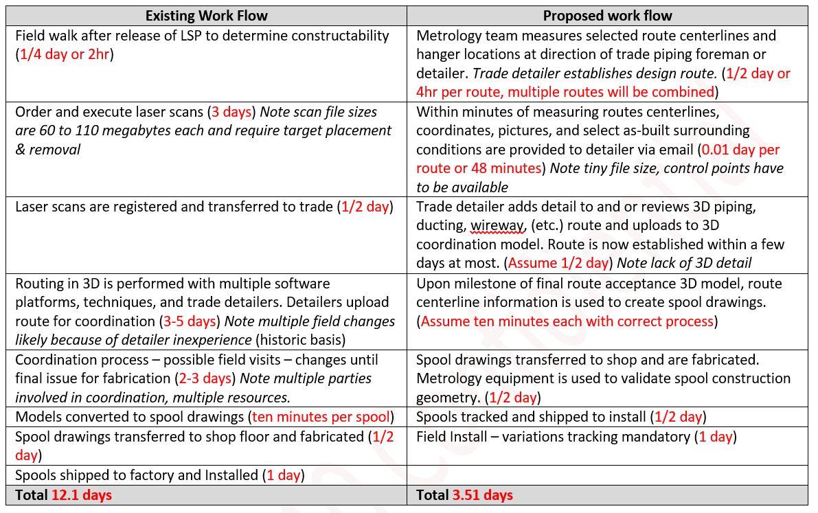
Durations, Existing vs. Proposed
A table comparing the existing and proposed work flow with durations (days) in red if you were to displace the traditional BIM process.
 .
.
 .
.
Description of Activities and Process (Optional Reading)
Equipment list: Leica AT-960 laser Tracker, with T-probe and full suite of support accessories. Leica 3D Disto also with full suite of support accessories. Software specific to the AT-960, standard software for the 3D Disto. Notebook computer with software specific to metrology tasks in this workflow. For example I’ve written custom applications to create 3D centerlines from coordinate lists.
Three person crew arrive at LSP field walk (or other work task). Equipment assembly, warmup and computer/I-pad network set up/boot up will take 15 – 20 minutes initially (same to put everything away in the cases). It takes any trade that long to enter a subfab given all the cleaning procedures.
Any measuring will requires “survey resection” procedure to establish the Tracker/Disto coordinate (position) from sub-fab control points (brass, targets). This will take anywhere from 1 to 5 minutes on average. Every time you move the tracker or Disto this will take 1 to 5 minutes for the Disto, and ten minutes for the tracker, as the tracker goes through a mandatory calibration sequence requiring nine minutes.
The Tracker will stay on the concrete slab floor. Because the Tracker is so expensive, weighs 28 lbs., and has a bulky form factor, it will not be used “remotely” at high elevations. Any FPOC’s on catwalks will be located by raising the tracker high enough to “look” down the catwalk grating.
Smaller (non-Leica) trackers are available and should be evaluated.
The 3D Disto has a small form factor, and weighs six lbs. It will be used anywhere the tracker would be and up in high remote hard to reach areas. The constraints are human accessibility of the actual placement of the unit. If a person cannot access the space and set up the magnetic or mechanical base to attach the Disto it cannot be used. The Disto measures (operates) by remote control from the I-pad/notebook. You control everything from the onboard camera of the 3D Disto (and or tracker) from the I-pad/I-phone applications. Both measure non-line-of-sight points, i.e. offsets. The tracker measures offsets with a T-probe very accurately (0.002 in) and very fast (less than a sec). The Disto is not as accurate on offsets, ( +- 1~2 mm) or as fast (three to five seconds).
The tracker requires an operator at every point being measured with the T-Probe. The T-probe uses multiple length probes (i.e. 25 mm ~ 600 mm) accurate to 0.01”. A small prism (reflector) can be mounted to a pole. The accuracy of such a method is the radius of the reflector or one half an inch. The tracker measures to the center of the reflector.
The measuring team should be managed (instructed what to measure) by piping detailers/foremen. The same concept applies when routing duct & electrical wireways, the foremen or detailers should provide the proposed routes. These suggested route may be memorized, marked with tape, string or method as determined by the crew.
Points where the route changes direction, elevation, turns are recorded by measuring that location. Field notes are “associated” with the measured coordinate to clarify the coordinate. The location of the Pop-Out penetration, Facility Point Of Connection, hanger placements and or any other important or significant place in space is measured and described. At any time the operators can convert the points into a 3D line, even extrude a circle, square, rectangle around it and email it directly to the office detailer using wireless secure internet connections in five seconds.
Software analysis can be performed in the field by the person measuring the point’s whether the route is within the correct routing zone, or outside the correct routing zone. This analysis can also be done by the office detailer. To be clear, if the point being measured is not in the correct zone an alert would trigger.
The process of measuring the route will be accomplished using a number of techniques including but not limited to:
- Directly measuring from any unistrut (or offsetting from any unistrut)
- Mounting remote control measuring equipment to unistrut o The catwalks, any FPOC
- Climbing up a ladder o Climbing up a ladder and on to a workmans plank.
- Holding a lightweight rod with small one inch reflector mounted to it.
- Measuring two points of a lightweight plastic rod offset from a point
- Directly measuring any point and offsetting it 90 degrees i.e. unistrut in ceiling slab 10” down, or unistrut in column and 8” away from face of column.
- Measuring selected first of kind & “first to arrive” tools before they are set in cleanroom. Establish TPOC’s for tools to reduce under RMF install times.
These techniques apply to any existing condition or newly installed material, or as-built conditions can be emailed to detailers as quickly as teams can set up and measure/photograph conditions.
In order to maintain accurate timely electronic records process will use a moleskin smart writing system (or equivalently capable system) for all written field notes. Or use the text to speech application on any smart phone.
Additional benefit, these teams can place control for laser scanning crews. A Leica Blk-360 laser scanner can be used in conjunction with this process to supplement coordinate information.
This process quickly provides accurate information to the office detailer as directed by the field foreman of the trade preforming the work.
This metrology work flow is not meant to displace other methods in place by the trades. We intend a pilot study be executed to;
1) Demonstrate the tracker can QC spools during fabrication by visiting the local fabrication facility
2) Show a 3D Disto used in the fab shop to layout spools.
3) Show the designer to import the 3D design geometry directly fabricate on the shop table.
4) Validates the geometry is correct (within tolerance) before shipment to field.
Initially this work flow could be used for the difficult, critical, long lead and prefabrication production work.
This is about insuring the work get done in time, accurately and safely with a smaller labor footprint in the subfab. We should move more labor into the fabrication environment where the spooling occurs.
Video overview
General 6:35 min overview movie conveying concepts.
If you can not view this video please; 1) enable JavaScript, and 2) consider upgrading to a web browser that supports that supports HTML5 video.
Select for HTML5 video support help
----------{End 8 minute section}----------
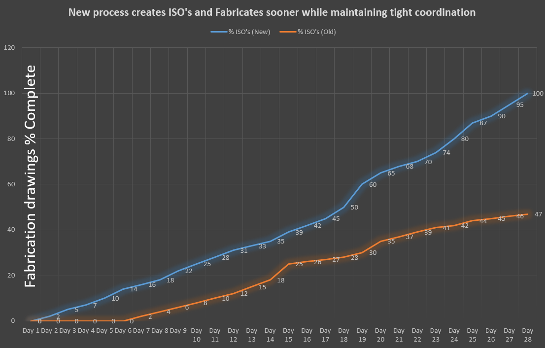
A side effect of adopting this process is schedule accuracy, predictability, and production rates. You know more about the supply chain state, what is mapped, fabricated, installed.
Page presenting offsite fabrication pilot overview
Tool Install Applicability
The 2018 Tool Install will require more modelling resources than are available to the trades. Traditionally, resource constraints compromise cost/schedule. This new proposed workflow supplements existing and available manpower to shorten the coordination and fabrication phases. A displacement/reduction of Laser Scanning and 3D modelling occurs by having trades more responsible to map and fabricate utilities without the overly detailed 3D models used for coordination. Coordination still occurs, it's moved forward significantly by using software automation. Metrology solutions extend to the QC process assuring accurate fabrication. The objective is to stop modelling stuff that's not necessary and control the placement of material more precisely.

More return with same effort
Equipment installation requires measuring for layout, and recording as-builts. Historically, trades have not recorded accurate as-builts. We'd have as-builts if there was an easy low cost near effortless process available. A byproduct of this process is accurate as-builts.
The more critical the measurement, in terms of accuracy, the more costly that measurement becomes. Measurements are normally 3D points, an X,Y,Z coordinate. It stands to reason the more 3D points we can "set" and record in a work day affects the cost per point.
Premise
So volume of points can be proportionate to cost. (not as applicable to laser scanning points)
As accuracy increases so does cost.
Though this article focuses on complex semiconductor factory conditions these metrics apply to any construction project. In the end it’s about selecting the right tool for the task at hand.
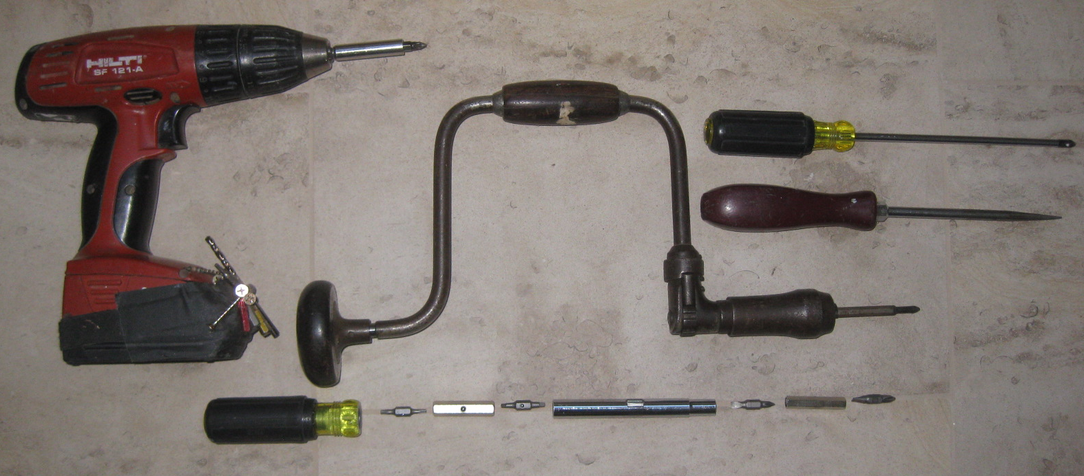
Each tool turns a screw, each has a cost, work capacity, and capability. Each serves a purpose and has it's place in a process.
Measurement methods
Let's examine seven methods of measuring and recording 3D points.
- Hand measure with tape
- Tape, Laser plumb & level
- Angle & distance survey instrument (mechanical)
- Angle & distance laser instrument (robotic)
- Laser scanner w/photo
- 3D Disto
- Laser Tracker w/Lucrosol Software
Each method has costs, accuracy, and production characteristics. The intent of this article is to agree on general concepts and apply some commonly accepted observations and historical experiences to get an idea of how much it costs to measure a point with each method.
Accuracy, precision, is a function of the equipment. Any single measurement can have a very adverse effect on construction, therefore, work flow or process must produce reliable accuracy.
These measurement methods involve people (Labor), and tools (Hardware), using a method (Process). There is cost associated with Labor & Hardware, and Process has time linked to production in the form of 3D points measured or marked, as layout. By comparing the cost of Labor, Hardware, Process, and time/production values we develop an understanding how much it costs to: 1) accurately measure a point, and 2) mark an accurate point.
Note:
Labor cost tends to be easily defined for our study, the person producing the work costs the employer dollars per hour. It should be noted that trade cost and owner cost will be different. (Owner cost would not contain profit, and have different overhead)
Hardware cost can get complex so to keep it easy we’ll use an equipment cost on a 36 month lease, 6% interest, five year life calculator.
We’ll treat “Process” as the container for the effort it takes to record, sketch, describe, place markers or targets, transfer data, etc. As we develop a better understanding of the process aspects of the measurement process will take on more complexity. In the short term we’ll keep it simple.
For this study we’ll define a Time/Production as a value of work, how long will it take to execute a defined amount work. Intent here is directed toward semiconductor factory work. Two types of work shall be defined, 1) setting points for equipment & pipe routing, 2) measuring clear pipe routes in a maze of existing piping. Readers should note these methods should used to validate spool geometry in fabrication. Without a validation procedure we increase risk of our parts not fitting.
We’ll need to quantify those values, the metrics of each method, something like this: (Select to expand)
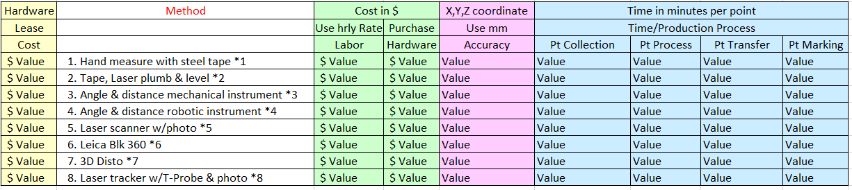
| Rationale & explanation (Terms & Definitions) | |
|---|---|
| TERM | EXPLANATION |
| Hand measure with steel tape | All measurements would be measured with a tape measure. No angles, other than a best guess could be accurately recorded or set. You could measure from control or target if close enough. |
| Laser Plumb & Level & distance meter | Add laser distance meter plus plumb multi axis laser horizontal & vertical lines as well as tape measure. |
| Angle & distance mechanical instrument | Survey grade mechanical transit capable of very accurate angle measurements. Distances would need to be measured by tape or distance meter |
| Angle & distance robotic instrument | Survey grade mechanical/electrical transit capable of very accurate angle, distance, scanning measurements. Very accurate line of sight measurements. Photographic capabilities. |
| Laser Scanner | Laser scanner. Cost & Accuracy vary. Overhead of processing, additional labor, data size |
| Laser scanner & hand scanner | Add hand held scanning device to laser scanner. Add burden of calibrating hand scans to laser scans. |
| Blk 360 | Leica small very portable tripod mounted scanner with wireless interface and improved registration process |
| 3D Disto | Leica small very portable remotely controlled robotic with wireless interface, camera, angle & distance measuring capabilities within 2-3 mm for 30 m. |
| Laser Tracker | Laser trackers are instruments that accurately measure large objects by determining the positions of optical targets held against those objects. The accuracy of laser trackers is of the order of 0.025 mm over a distance of several meters. |
| Hardware cost | As equipment amortization can get complex, and we are attempting to compare complex configurations of hardware software we are using the cost to own over three years all hardware and software. This cost will vary by company. |
| Accuracy | All measurements are plus or minus. For practical matters you cannot measure more accurately than 2 mm, the exception being a laser tracker (in my opinion) |
| Pt. collection (measuring) | Taking a field measurement. This can be fast or slow depending on what you are measuring. In many cases a ladder, pole, or other assisting equipment will be required. |
| Pt. process (processing points) | When recording a measurement, notes, sketches, electronic transfer setup, post processing of point cloud data to local coordinates will require special computers, software, and skill. |
| Pt. Transfer (transferring points) | After a sketch, finished notes, files of point values, or laser scans are complete they need to be provided to the detailers. In most cases this can be performed in email. In the case of laser scans the transfer will take many hours. |
| Pt. Marking (Setting points in the field, layout) | Various methods of marking a point in the field include black ink on white tape, which takes time. |
| Precision | FULLTEXT01.pdf |
Difficulty of measurement “Add-on” criteria
Our field environment has specific areas which are difficult to access. (like all projects) So we will assign a difficultly factor, defined as “time”. This time metric will be applied where as appropriate. (Select to expand)
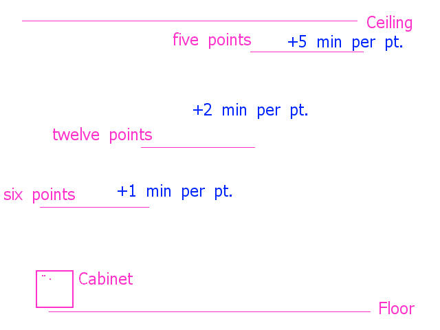
Test route defined - Difficulty of measuring pipe routes (i.e. add 145 min to test route time)
Explanation: One point for cabinet, 23 points for the route will be the production criteria. Two of the route points will be starting and ending point of pipe, five will be twelve feet above the floor, twelve will be from eight feet to eleven feet above the floor, and the remaining six will be from the cabinet to seven feet above the floor. Higher points are more difficult, so extra time (1, 2 , & 5 minutes per measured point) is added.
Please note, Until actual field times are "averaged on field expirences" we will apply difficulity factors, for example, the only two hardware items easily placed in tight high factory areas are the Leica Blk 360 & 3D Disto, measuring with others requires creative methods (more time) to both measure and tie into control
Quantifying each method
Having defined the methods let’s look at some tables and charts of values.
Hardware, equipment cost per hour
| Equipment cost | ||
|---|---|---|
| METHOD | HOURLY COST | PURCHASE COST |
| 1* Hand measure with steel tape | $1 | $100 |
| 2* Tape, Laser plumb & level | $3 | $1,000 |
| 3* Angle & distance survey instrument | $3.41 | $27,000 |
| 4* Angle & distance laser instrument | $6.83 | $54,000 |
| 5* Laser scanner w/photo | $12.65 | $100,000 |
| 6* Leica Blk 360 | $1.90 | $15,000 |
| 7* 3D Disto Droid | $1.13 | $9,000 |
| 8* Laser Tracker w/Lucrosol Software | $32.91 | $260,000 |
Using 6% interest, 36 month lease, 5 year life (http://fitsmallbusiness.com/equipment-lease-calculator/)
Method Notes:
*1 Not usable method – realistically should not be a method, used to show how expensive a useless method can be
*2 Usable in 10% of some cases. Little consideration will be given
*3 Entry level usable, takes lots of labor to operate - Low cost - dependable - moderate level of skill
*4 Very usable labor and maintenance to set up operate, learning curve. Expensive - higher moderate skill level
*5 High skill level, high cost, easy to introduce error, requires post process team with hardware and software, large file sizes, moderate accuracy
*6 Not Shipping but projected
*7 Essentualy a full featured robotic total station with camera and CAD software, can measure outside line of sight with offest rod
*8 $$$, requires higher cost labor, can be single man operation, precise, measures outside line of sight
Accuracy
| Accuracy in mm | |
|---|---|
| METHOD | mm |
| Hand measure with steel tape | 5 |
| Tape, Laser plumb & level | 4 |
| Angle & distance survey instrument | 3 |
| Angle & distance laser instrument | 3 |
| Laser scanner w/photo | 15 |
| Leica Blk 360 | 12 |
| 3D Disto Droid | 2 |
| Laser Tracker w/Lucrosol Software | 1 |
Accuracy Conclusion
From these metrics we observe the most accurate method is the Laser Tracker hardware / software solution. Therefore the best choice for an off-site fabrication scenario. Further, it should be understood that deploying a solution like this is specific to high risk materials like electro-coated & specialty coated metals, any critical or expensive items. It makes little sense to use a method like this for low risk, plastics, and flexible materials.
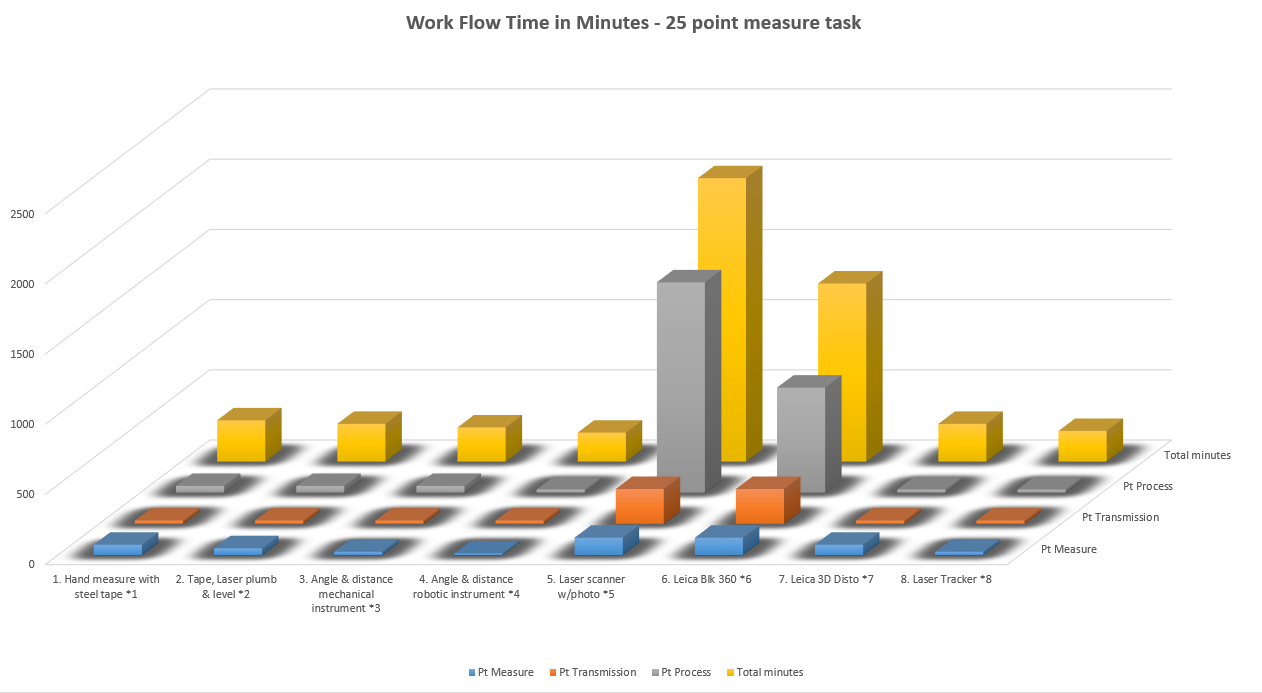
Time in Minutes to measure – collect data – transfer data
How long in minutes does it take each method to field measure a twenty five point pipe route? Steps include the difficulty of access, actual measurement, calibration to fab control, and transfer to the end user. Laser scans have the burden of longer “set up” and transformation processing after the scan is complete. (Tie scan to control). Laser scan technologies only record and cannot be used to preform “layout” so that must be noted.
| Workflow Time in minutes | ||||
|---|---|---|---|---|
| METHOD | total minutes | measure | record | transmit |
| Hand measure with steel tape | 295 | 75 | 50 | 25 |
| Tape, Laser plumb & level | 270 | 50 | 50 | 25 |
| Angle & distance survey instrument | 245 | 25 | 50 | 25 |
| Angle & distance laser instrument | 207 | 12.5 | 25 | 25 |
| Laser scanner w/photo | 250 | 125 | 1500 | 250 |
| Leica Blk 360 | 1270 | 125 | 750 | 250 |
| 3D Disto Droid | 270 | 75 | 25 | 25 |
| Laser Tracker w/Lucrosol Software | 220 | 25 | 25 | 25 |
Time required to measure a twenty five point route, process the information and transfer to detailer. (Select to expand)
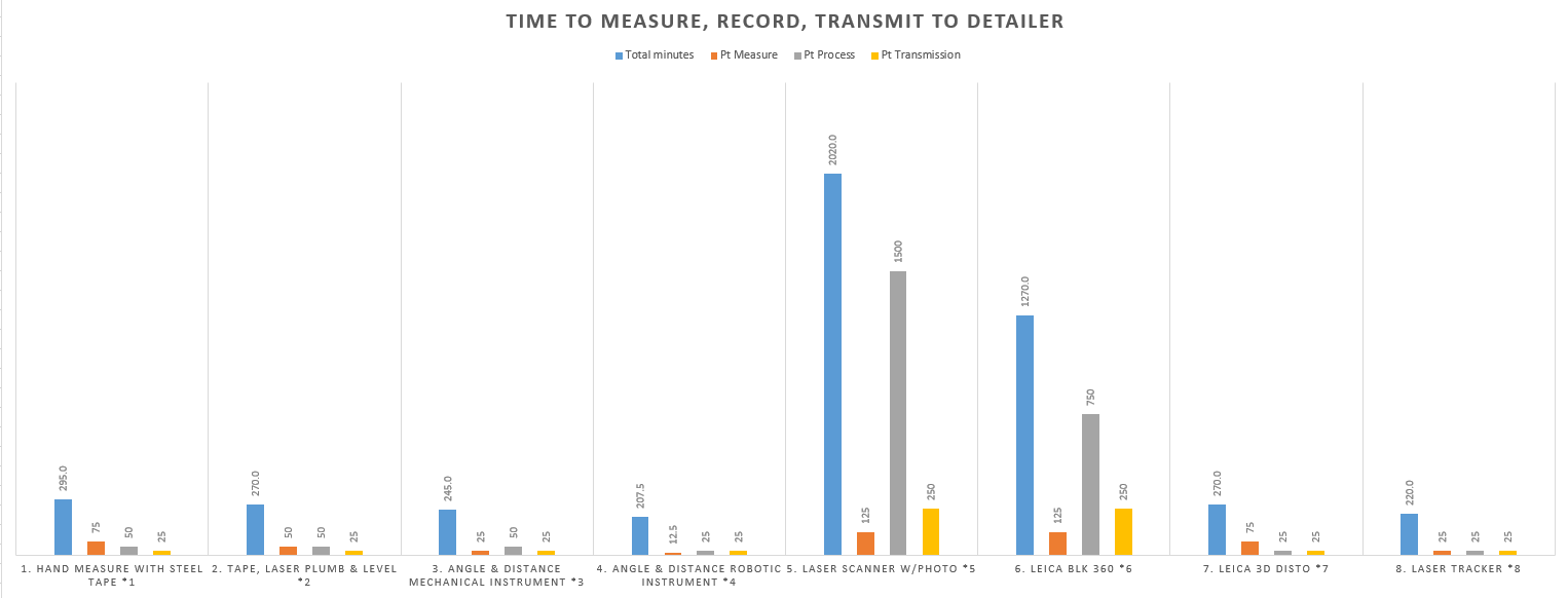
Time required to measure a twenty five point route, process the information and transfer to detailer.
Time Conclusion
From these metrics we observe the longest method is associated with laser scanning and the quickest method is the Laser Tracker. Therefore we conclude any effort to reduce to amount of labor is best served by the Laser Tracker.
You could not use method 1,2,3 5 or 6 to layout a route in the sub-fab.
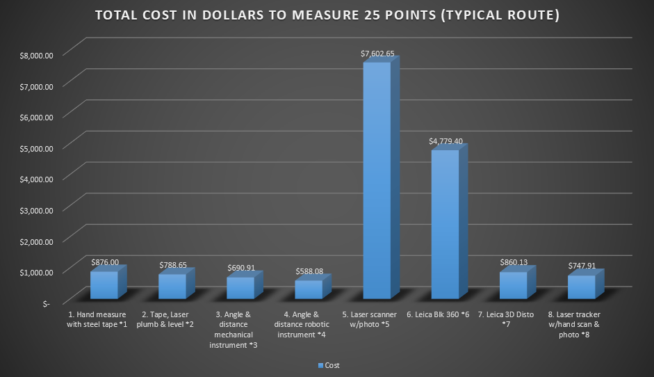
Hardware & Labor Cost in dollars to measure twenty five point pipe route (or preform as-builting)
Applying the labor rate and hardware cost to the time estimate we can compare method costs.
| Total hardware & Labor to measure Route (or As-built measuring) | |
|---|---|
| METHOD | Cost |
| Hand measure with steel tape | $876 |
| Tape, Laser plumb & level | $788 |
| Angle & distance survey instrument | $691 |
| Angle & distance laser instrument | $588 |
| Laser scanner w/photo | $7,602 |
| Leica Blk 360 | $4,779 |
| 3D Disto Droid | $860 |
| Laser Tracker w/Lucrosol Software | $747 |
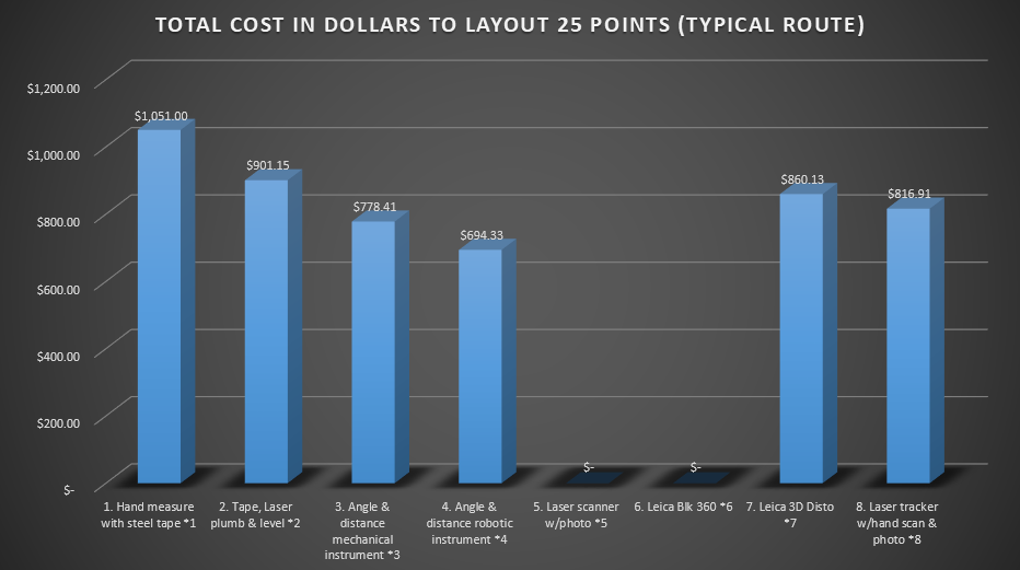
Total hardware & Labor Layout twenty five points
Labor cost in dollars to mark twenty five points
| Total hardware & Labor to Layout Route | |
|---|---|
| METHOD | Cost |
| Hand measure with steel tape | $1,051 |
| Tape, Laser plumb & level | $901 |
| Angle & distance survey instrument | $778 |
| Angle & distance laser instrument | $694 |
| Laser scanner w/photo | N/A |
| Leica Blk 360 | N/A |
| 3D Disto Droid | $860 |
| Laser Tracker w/Lucrosol Software | $816 |
Overall Conclusion
Combining what we understand a few conclusions should be considered. Let’s outline what we believe to be true.
Hand measuring without very accurate equipment of some sort cannot be considered as viable.
Angle and distance mechanical transits are dependent on:
- line of sight
- measuring distance with secondary methods like steel tape or laser distance meters.
Robotic total stations are:
- constrained to line of sight measurements
- can provide valuable photographic and very course limited scan points.
- are very accurate.
The data sets of transits and total stations even when combined with their scan and photographic capabilities is small enough to email quickly.
Total station data (coordinates) can be collected and preregistered to site coordinates. (very important!)
Laser Scanning:
- Of any type cannot be used to set, stakeout or layout equipment or pipe routes.
- Is expensive requiring multidiscipline skills, software, and capable computers.
- Accuracy is determined by 1) hardware equipment quality and the calibration, 2) post processing transformation to control software process.
Historically laser points can be found inside and outside of the actual concrete & steel surfaces raising precision issues.
3D Disto
- Light enough and small enough to safely use in high areas of sub-fab.
- Can be placed and operated remotely
- Provides pictures
- Can resection, set to site coordinates
- Can offset for measuring non-line of sight.
- Perfect for use with Tracker - does what tracker can not up high and in congested areas
- Quite accurate
- Could possibly replace tracker - but will be slower to operate
Laser Tracker:
- Are very expensive.
- Are very accurate. (A properly calibrated tracker will repeat all distance measurements within +/-0.0020”)
- Can provide very limited (small areas up close) high density scanning capabilities.
- Can stakeout pipe routes and equipment.
- Are not constrained to line of sight measurements.
- Data is small enough to email.
- Use costs are in line with other methods.
This same process and equipment easily confirms as-built – prefabricated utility sections, piping, wireway sections, duct sections. Additionally this equipment preforms layout for the fab shop. The fabricators can use this equipment to precisely build their utilities by displaying the 3D model geometry on to a table top, confirming placement before welding, or fastening sections.
Note:
While many route layouts, as-built mapping & point collection in general will not require extensive photographic information (beyond static photographs) there will be situations where full video is helpful to the detailer. In those cases we can provide 1) video files of the route environment, 2) streaming video of the environment to the detailers desktop. This option permits the detailer/pipefitter/foreman to make routing decisions quicker and confidentially.
In the opinion of the author, combining one or two laser trackers with ten 3D Distos could reduce tens and tens of subfab labor and Office modelers. The work flow of providing fast accurate routing information (centerlines) to less detailers is very attractive. Knowing the spools match these field measures centerlines reduces risk of rework. Improving fabrication layout methods and quality control process is desirable. Handing control back to the trade experts who install is more efficient. Removing as much unpredictability from Tool Install routes will smooth out some of the coordination headaches. This work flow reduces head count, and time required to fabricate materials.
(Investigate possible use of barcode labels for control points. Determine if Disto secure point photo of barcode could be "read" allowing automatic coordinate transfer to computer.)
General Overview Powerpoint Presentation movie
1:30 min General Concept video. No sound powerpoint. If you can not view this video please; 1) enable JavaScript, and 2) consider upgrading to a web browser that supports that supports HTML5 video. Select for HTML5 video support
Big Picture Concept Powerpoint Movie
1:51 min Big Picture overview. No Sound. If you can not view this video please; 1) enable JavaScript, and 2) consider upgrading to a web browser that supports that supports HTML5 video. Select for HTML5 video support
Measurements and layout files
The foundation of our workflow is having small precise flexible information. ASCII text files of measured point (coordinates) can define quite a bit of useful routing, layout, or existing conditions when combined with descriptions and pictures.
This workflow is not meant to replace legacy laser scanning or other processes the trades incorporate in building, it’s meant to reduce long lead and higher risk material placement. These metrology solutions should be used to validate the as-built sections produced at the (off site) fabrication facilities before they ship for install. Eventually these metrology solutions will displace a significant amount of laser scanning before they themselves morph into another process or get replaced by an improved solution.
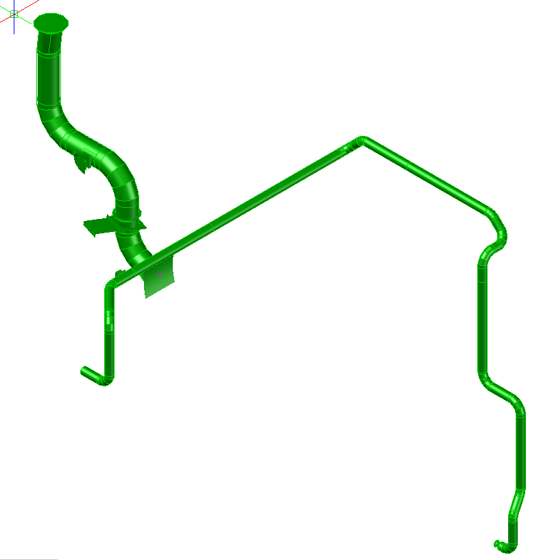
Below is an example of the deliverable emailed to the detailer. This is an example if two mechanical duct coordinate centerline files.
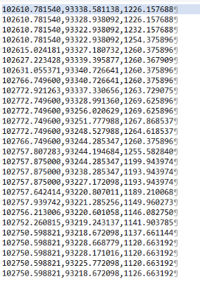
Select for larger image
Below is an example of the same file with descriptions.
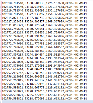
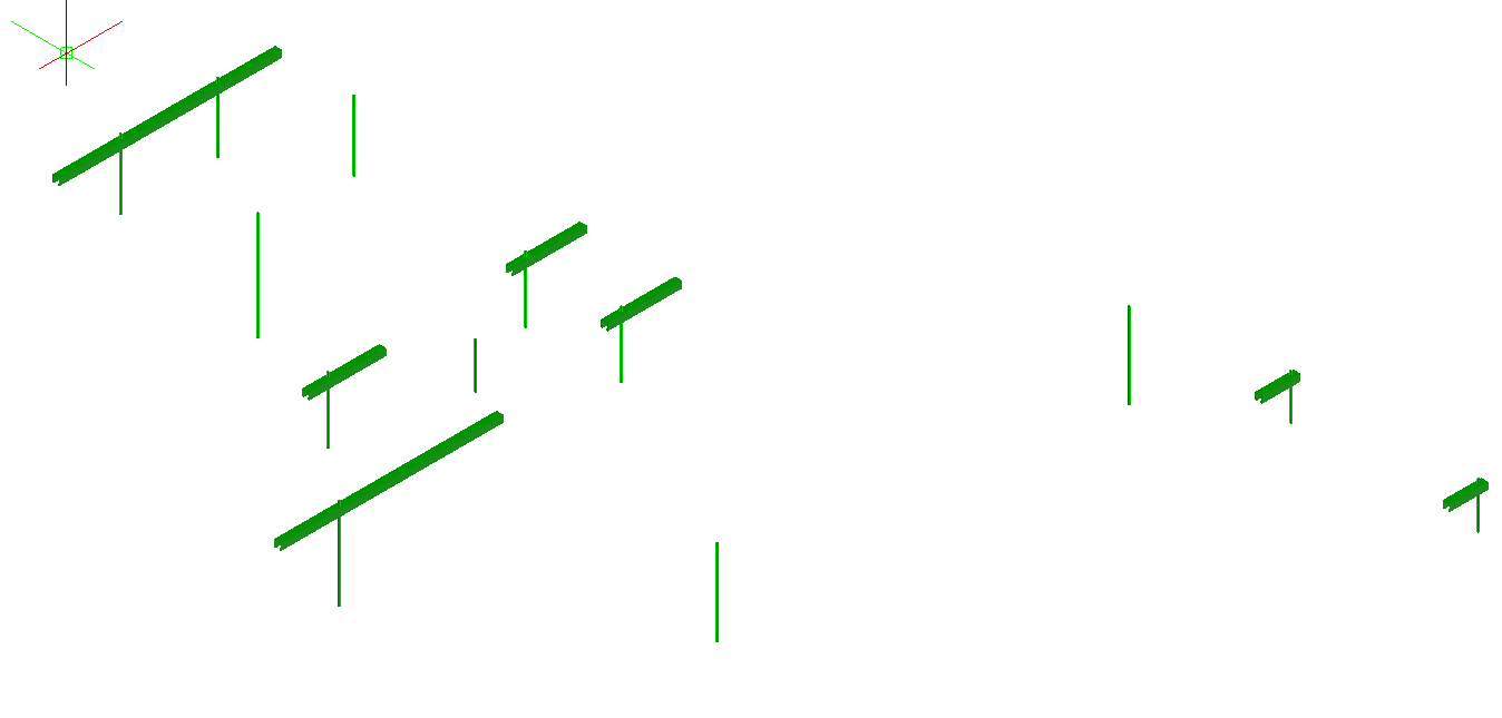
The detailer can import the ASCII files into their native software, i.e. AutoCAD based products, as well as Intergraph & Solidworks or other software lines. Below we see the coordinate files converted to 3D points in AutoCAD.

The coordinate files will also be provided to the detailers as 3D lines. Below is the same example of two mechanical ducts as 3D lines.
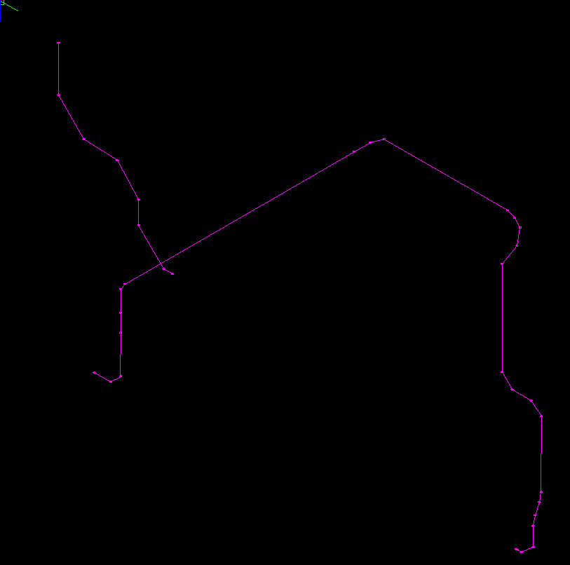
Detailers will use one of the measured centerlines, (note trade foreman or pipefitter approved the route from the LSP supplied) to create a 3D file of their utility for coordination and or fabrication.
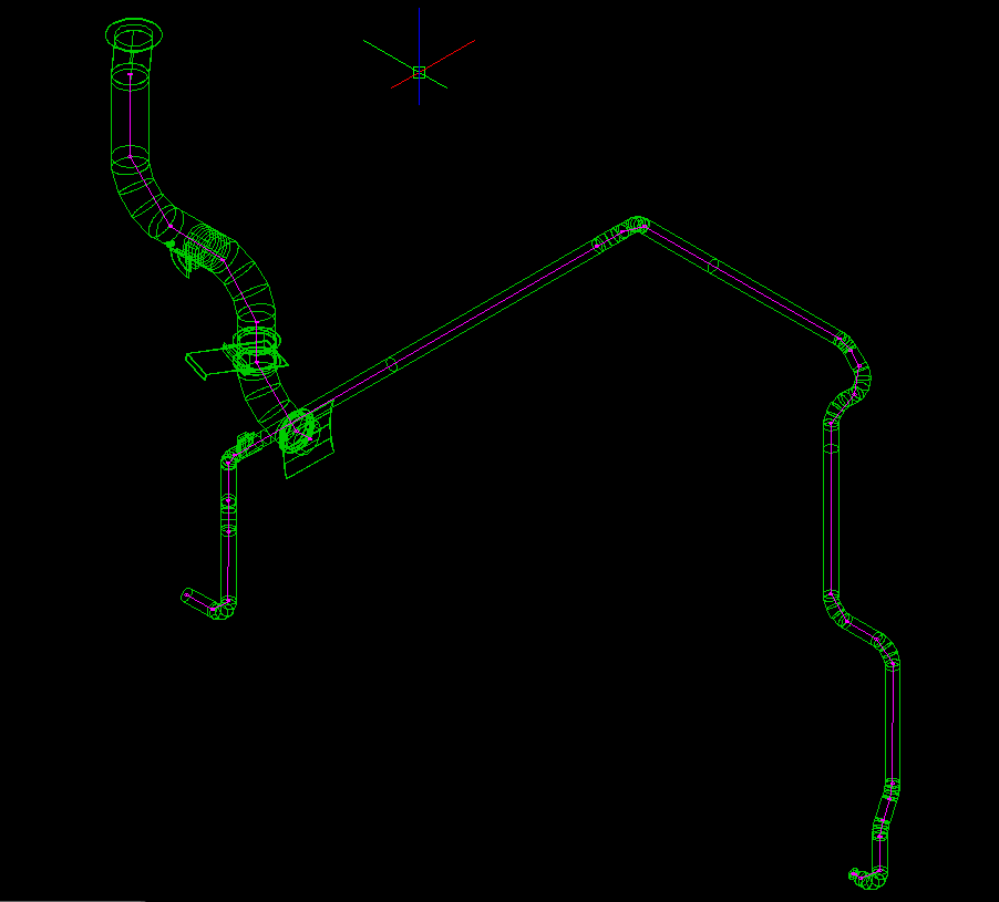
The coordinate/3D line route data supplied can be as detailed as the trade/owner see fit. This information can go directly to ISO’s / spool files for the fabrication shop. Her we see the two ducts detailed out in AutoCAD Mechanical software.
Also worth knowing is the hanger locations can be mapped with the same metrology solution. Trades could create work flows specific to their utility support requirements and implement them to speed hanger packages as well as utility shop drawings. Below we show a hanger package drawing in 3D form for the two mechanical ducts.
Detailed View of partial process featuring laser scan data
2:42 min Detailed overview movie. A step through of the workflow explaining laser scans and the Disto / Tracker use. Explains Laser Scan vs. point mapping, and instrument size. If you can not view this video please; 1) enable JavaScript, and 2) consider upgrading to a web browser that supports that supports HTML5 video. Select for HTML5 video support
16 Sec movie of two workflows. The old fabrication workflow is compared to the new workflow. For easy reading expand to full screen. To focus on either of the two pages please select pause/play. If you can not view this video please; 1) enable JavaScript, and 2) consider upgrading to a web browser that supports that supports HTML5 video. Select for HTML5 video support
Overview of Leica 3D Disto AKA Droid
http://carbon-xl.com/camera_crane.aspx (Carbon XL site, camera accessories - example)
30 Sec movie with sound of mounting to popout slab. A light carbon mount can be attached to unistrut. For easy reading expand to full screen. To focus on either of the two pages please select pause/play. If you can not view this video please; 1) enable JavaScript, and 2) consider upgrading to a web browser that supports that supports HTML5 video. Select for HTML5 video support
Link to typical generic magnetic mount, link1, link2, Magswitch Technology, Simple Base, Magswitch catalog, McMaster, Seco 5114-052 Switchable Kelly Magnet Mount.
Laser tracker use in industry:
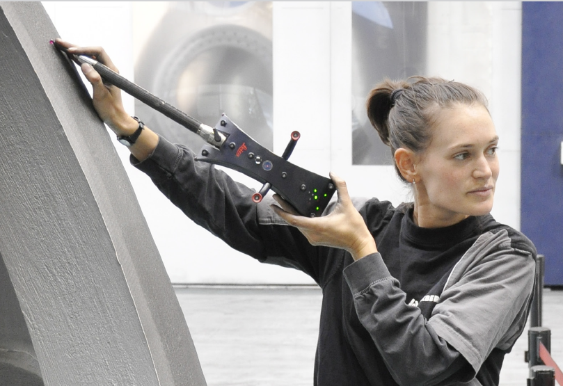
"Laser Tracker T-Probe" measures out of sight points
Public Case papers:
General Overview. 1:15 min. Movie showing use cases. If you can not view this video please; 1) enable JavaScript, and 2) consider upgrading to a web browser that supports that supports HTML5 video. Select for HTML5 video support
NOTE: Term “inaccessible” area is defined as not within line of sight in these summaries.
Aero LTD – Airbus, used to inspect engine pylon mount components made of titanium. Used to validate “exact” fabrication for fitting to airplane. Fifty four points per pylon are measured. Points are inaccessible and difficult to access. The T-Probe is utilized.
Red Bull – Auto, used because they have no time for mistakes. Used to check dimensional integrity of a new component. Tracker with T-probe is used because inaccessible areas require precision measurements.
Sakana – Foundry, builds large components for ships, wind turbines, “on-site” because of transport issues. Quality control and layout require precision and ability to measure inaccessible areas with T-probe.
Vorarlberg – Hydro electric components (turbines) before new turbines are brought into operation, it is Ralf Laufer’s task to capture the exact shape of the turbine rotor for later investigations. Components are too large with too many inaccessible areas to measure with precision required.
Joint Venture research – Superconducting magnet component of experimental reactor in Cadarache, in southern France. The 22 turns of the double winding have to meet tolerances in the order of few tenths of a millimeter on the 3D form error, and the total length of the turn has tolerances of few parts per million throughout the full length, which is also the most complex size to be measured.”
BMW – Auto, A key goal for any new system was reducing operation time without sacrificing the precision and accuracy needed to properly identify production defects. Used for three reasons; Speed, precision, ability to measure inaccessible areas.
Alternative view
Here is another way of looking at what I’m proposing with this workflow. A tool install currently requires office 3D modelers/detailers which have been and remain in short supply. Training is possible but of limited production value and introduces error and omission to the process. Few 3D modelers have the depth of fabrication experience to perform their routing without significant guidance from senior members of the team.
To make it easier to route utilities laser scans were incorporated into the tool install process. This development essentially brought the subfab to the desktop design environment. 3D computer designers required additional software, more powerful computers, additional skill, and more time to master and use the laser scans to preform routing and essentially fabrication, installation.
For the cost and complexity Laser scanning provided marginable production and quality control benefits to the owners. Laser scanning provides high rate of return within less congested environments, however the congestion, inaccessible areas, shiny and small diameter materials within a subfab overwhelm the value proposition of laser scanning to the owner. The trades and laser scanning services love it because they make money on the process. Inherently laser scanning as solution to hanging pipe faster and more accurately is not without its challenges.
There appears to be a high value of return providing the essence of what laser scanning intends to provide the trade detailing team with – near irrefutable accurate routing and connection locations, coordinates.
Software packages like Autodesk Plant and Cadworx use library driven 3D modeling intent, the users select the actual parts to build their pipe, or utilities. These packages emulate the fabrication table process. When the 3D modeler is finished, the coordination amongst trades in the route area is complete / approved the routing data is sent to the fabrication shop as an ISO to be created from off the shelf parts.
To execute the above process faster is dependent of the coordinates of the route, the hanger coordinates (where can you connect a hanger), routing zone compliance, and other design factors.
We propose moving a portion of the Laser scanning & associated software cost budget to the field measuring process that emails routing coordinates to a smaller team (than laser scanning process requires) to create and clean up the 3D utility route, coordinate, and issue for fabrication. Our solution extends to the fabricator shop to assist with Layout & Quality control of spools by validating the as-built to design.
Any existing processes may remain in place. Should our workflow show desirable cost, schedule, and utility installation benefits to specific teams, great they can adopt them to maintain margins. Someone is going to do something like this so it might as well be you.
Discussion URL's (Links)
visualive3d - From former P1272 engineer
Motorcycle frame piping example - free forms
https://www.youtube.com/watch?v=W6su6Nb99Yo
4:48 minutes into movie
Overview of 2D laser projection as applies to pipe fabrication
Faro
2 min, 11 sec movie with sound of laying out any size pipe material from centerline data, thus eliminating shop drawings. For easy reading expand to full screen. To focus on either of the two pages please select pause/play. If you can not view this video please; 1) enable JavaScript, and 2) consider upgrading to a web browser that supports that supports HTML5 video. Select for HTML5 video support
Overview of 3D laser projection as applies to pipe fabrication
Faro
1 min, 10 sec movie with sound of laying out any size pipe material from centerline data, thus eliminating shop drawings. For easy reading expand to full screen. To focus on either of the two pages please select pause/play. If you can not view this video please; 1) enable JavaScript, and 2) consider upgrading to a web browser that supports that supports HTML5 video. Select for HTML5 video support
Twin Coast one
2 min, 41 sec movie with No sound of laying out any size pipe material from 3D model data, thus eliminating shop drawings. For easy reading expand to full screen. To focus on either of the two pages please select pause/play. If you can not view this video please; 1) enable JavaScript, and 2) consider upgrading to a web browser that supports that supports HTML5 video. Select for HTML5 video support
Twin Coast two
Second 2 min, 43 sec movie with No sound of laying out any size pipe material from 3D model data, thus eliminating shop drawings. For easy reading expand to full screen. To focus on either of the two pages please select pause/play. If you can not view this video please; 1) enable JavaScript, and 2) consider upgrading to a web browser that supports that supports HTML5 video. Select for HTML5 video support
Extend 3D one
Second 0 min, 26 sec movie with No sound of laying out any size pipe material from 3D model data, thus eliminating shop drawings. For easy reading expand to full screen. To focus on either of the two pages please select pause/play. If you can not view this video please; 1) enable JavaScript, and 2) consider upgrading to a web browser that supports that supports HTML5 video. Select for HTML5 video support
Extend 3D two
Second 1 min, 0 sec movie with No sound of laying out any size pipe material from 3D model data, thus eliminating shop drawings. For easy reading expand to full screen. To focus on either of the two pages please select pause/play. If you can not view this video please; 1) enable JavaScript, and 2) consider upgrading to a web browser that supports that supports HTML5 video. Select for HTML5 video support
Latest:
ATS600 Leica laser tracker with scan capability. $170k
Culture: TED talk
Note to self: Proprietary 3,4,5 with Z value process to transport/transfer coordinate systems.
Disto S910 exterior $2000
Autodesk TruLaser
https://www.ted.com/talks/amy_edmondson_how_to_turn_a_group_of_strangers_into_a_team
BIM implementation paper: